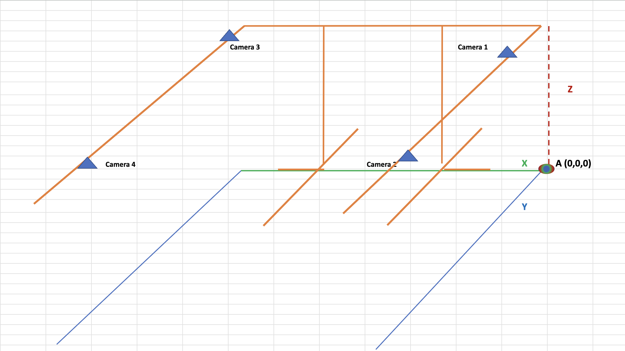
Before asking a question, I want to talk a little about what we do with ZED cameras. So, we have a large cubic stand (3m x 3m x 3m), in the upper corners of which zed2i cameras weigh. In the middle of the stand, there are scales on the floor, all this is used by the logistics company to assess the type of cargo, damage on it (we trained different ML models for this) and cargo dimensions
The whole system is controlled by ROS2 (we have asked questions about it before), we have one 6 GB gpu, so our ML models are load into memory if we use the ULTRA depth quality (not neural).
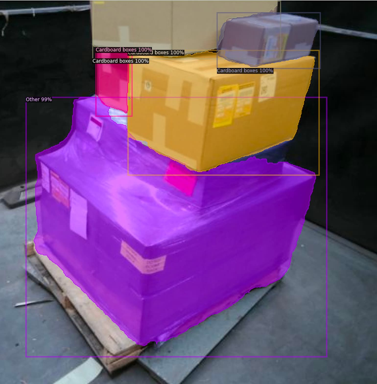
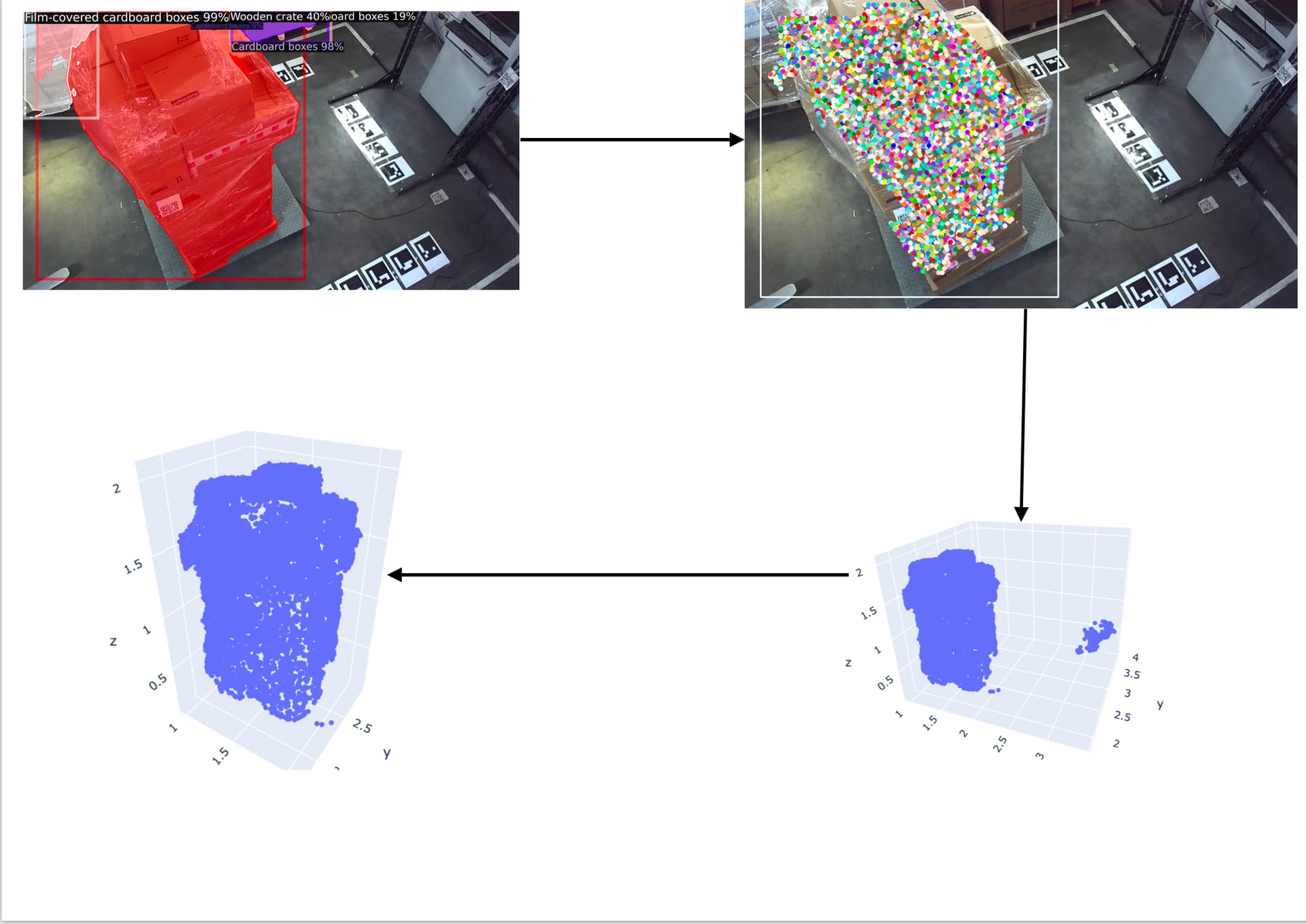
Well, the part of the pipeline related to sizing is not working well for us. After we have segmented the cargo, we estimate the depth to the points of the cargo within the segmented polygon and transfer those points to world 3D coordinates. We get transfer matrices after calibrating the camera to ArUco markers (we know in advance where these markers are located in the world coordinate system). And, of course, we use some postprocessing after we get point clouds from different cameras
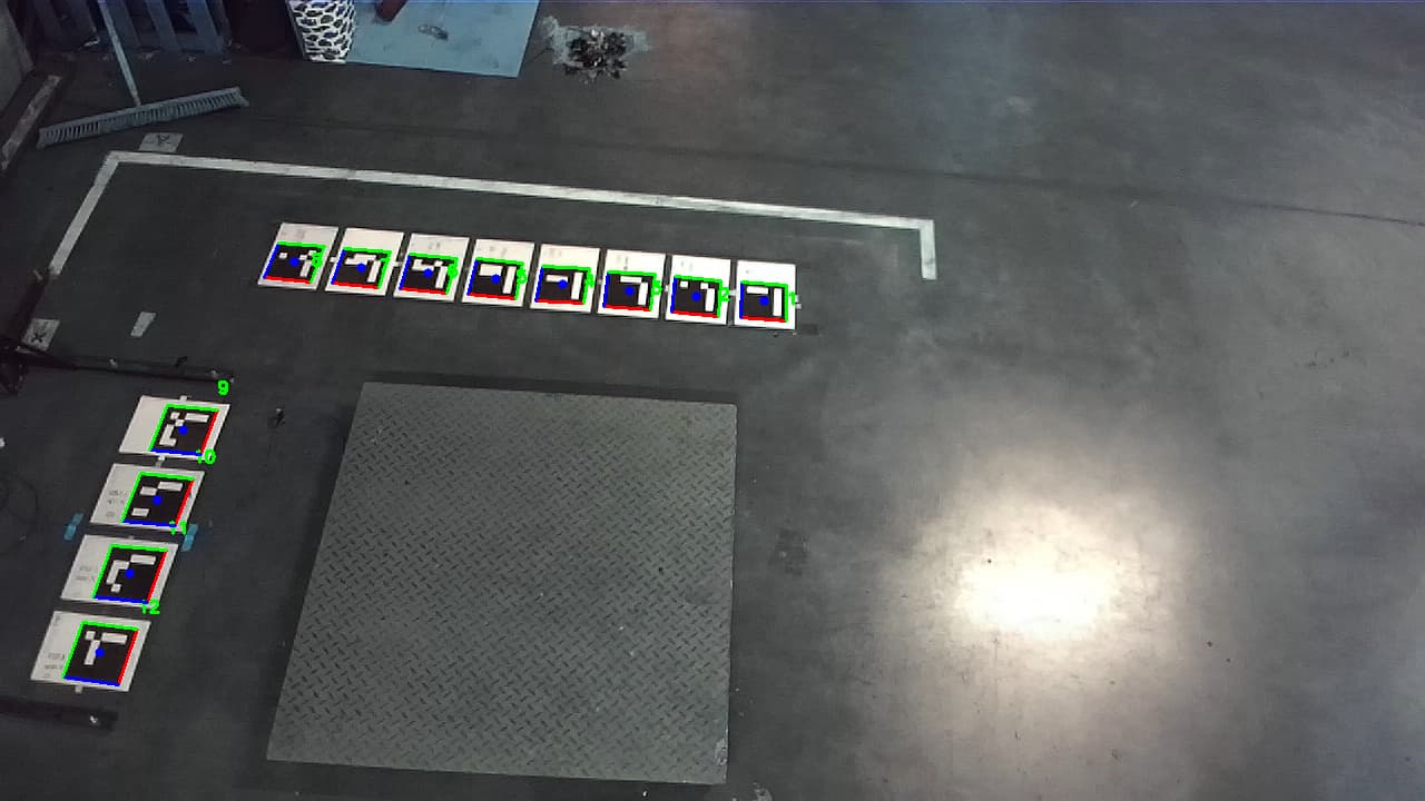
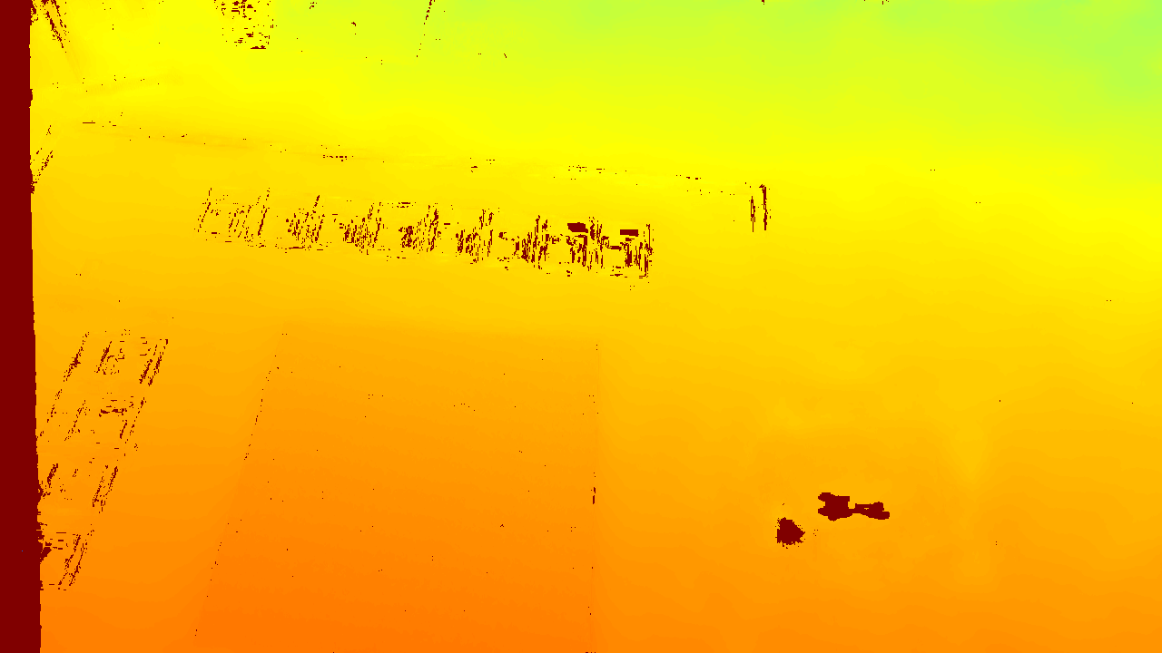
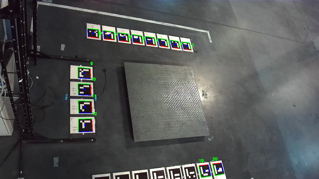
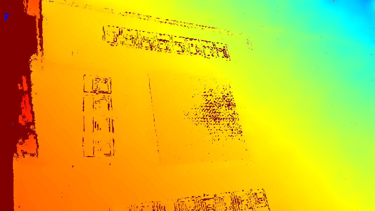
So, we found that the main problem is poor calibration - Zed2i is sometimes wrong by 12% when estimating the distance to the ArUco marker (for example: 4249 mm instead of 3803 mm). At the same time, there is no strict correlation that the farther the markers are, the worse the estimation of the distance to them, as if the combination of white and black on A4 sheet confuses ZED …
In the presented photos, the paper is laminated, but we had experiments with plain paper as well - the errors are approximately the same everywhere
What can you advise to do to increase the accuracy of depth estimation to ArUco markers? How much better would it be if I switched to ULTRA quality (I couldn’t find a quality comparison between different modes)?
Maybe i should tweak some Zed/ROS settings to improve the quality of depth estimation? (ArUcos are always in the same place, maybe this can somehow help zed cameras?)
In the ideal case, zed cameras are not fixed, and they can be moved (recalibration is automatic after system reboot), but if we fix them, can we help the depth estimates somehow by telling them the exact distance to each marker? Will the camera be able to “calibrate” to this information?
What are the prospects for solving this problem with Multi-Camera Fusion API? Will we need ArUco markers to synchronize the images with each other (obviously with them it will be easier to find correspondences between the cameras)? In what coordinate system will the Multi-Camera Fusion API upload point clouds? Will it be possible to say that all cameras will calibrate themselves and it will be possible to estimate the size of the cargo simply by pointcloud?
Hi @pixml
can you please record an SVO in the same conditions providing a ground truth of the correct distances of each ArUco marker from the camera and share it with us to support@stereolabs.com?
This will allow us to check the calibration status of the camera and provide you with detailed support.
Please link this post in the email, so we can keep track of it.
I am also working on a similar kind of problem. Could you please help me with how do I find the global position of the aruco markers. In on of the post, I saw that you have mentioned we need to use laser meter or metric string technique. Is there any other method also to determine the global position of the markers since I dont have the necessary tools for above?
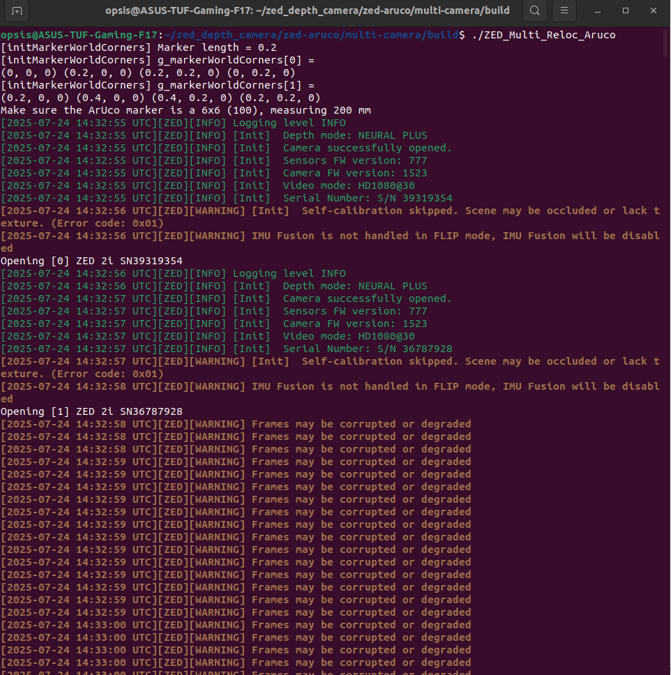
I have tried the multi-camera ArUco-based calibration approach using two markers from the 6x6 dictionary, each with a marker length of 200 mm.
In my setup:
Marker ID 0 is considered as the origin and placed at a visible location for both cameras.

Marker ID 1 is placed exactly 200 mm along one axis from Marker 0.

I’ve manually set the position of Marker 1 in code relative to Marker 0 (translation along one axis).
However, I am still facing issues:
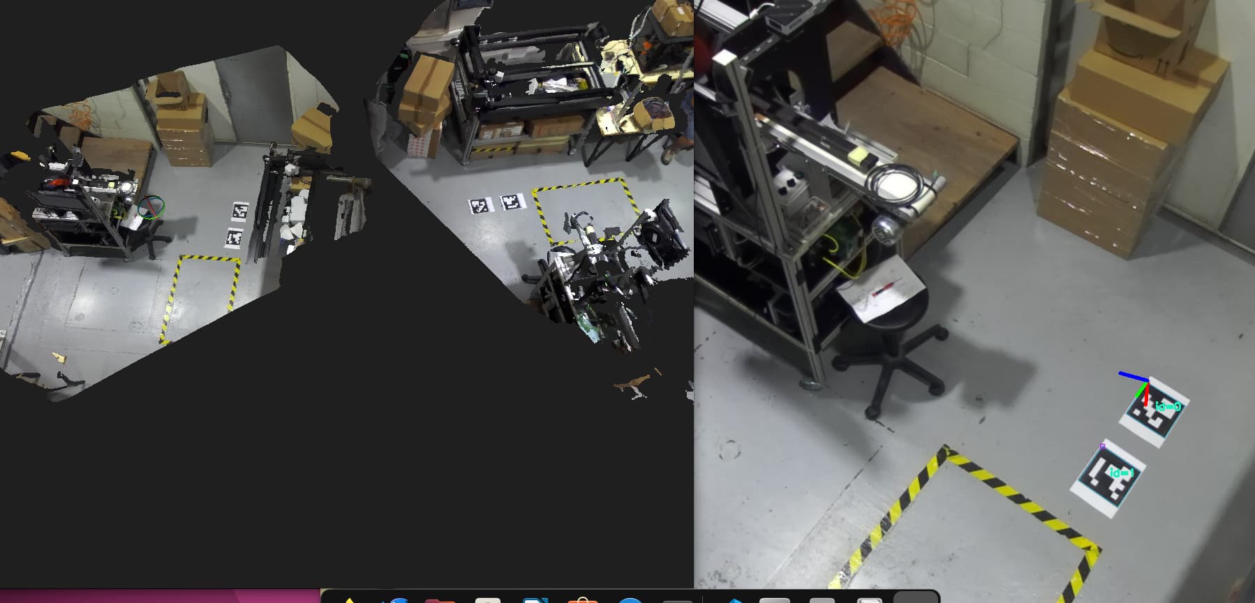
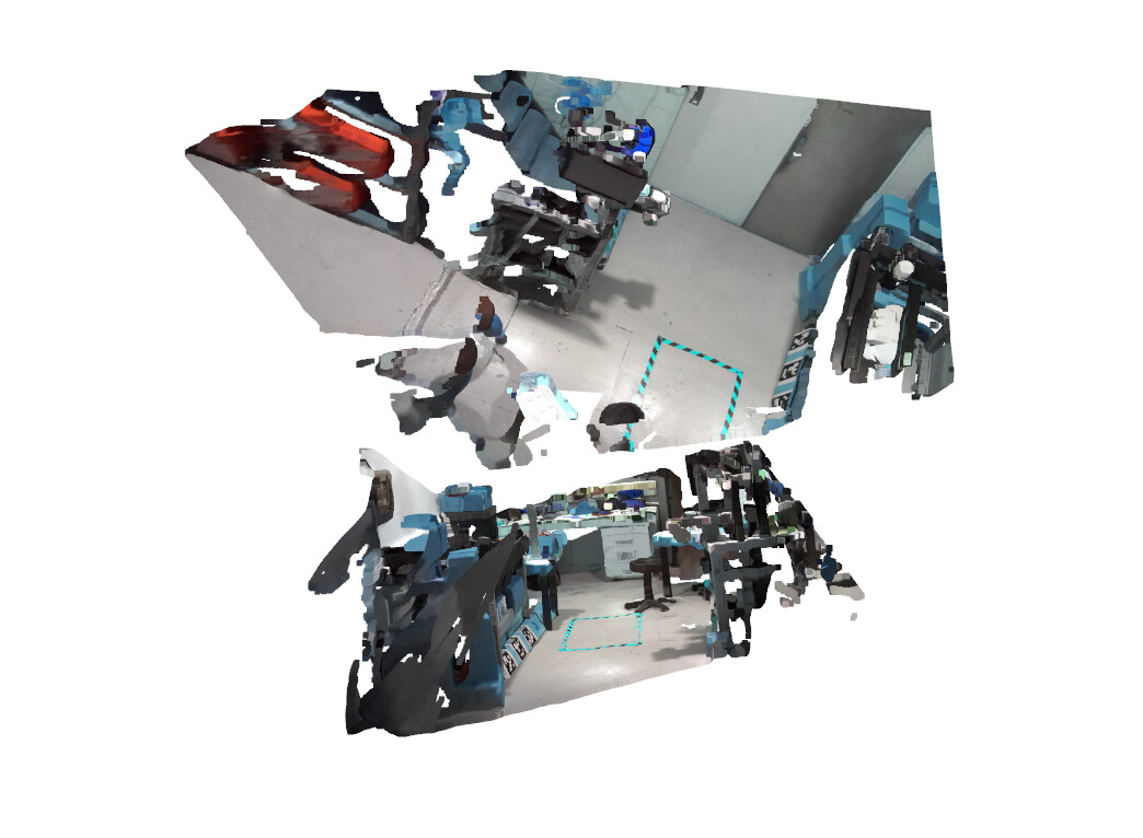
The fused point clouds are not properly aligned, especially noticeable in the Z-axis (floor planes don’t match well).

I’ve attached screenshots of the point cloud fusion result and terminal logs for your reference.
I am new to multi-camera calibration and point cloud alignment, so I would really appreciate any guidance or detailed explanation you can provide — especially around improving the alignment or any best practices when manually defining marker positions.
I am considering z-axis as the upper direction. I tried adding the offset in y component also but the issues were still the same. I am not sure if I modified my code correctly for zed cameras localization using multi-arucos.
I know I should ensure that my modifications are correct but I am unable to find if it is the problem of the code or cameras. Thats why I wanted to just verify my code. Today I tried my code with multiple arucos but still I ma facing the alignment issues in z-axis. It is not able to correctly match the floor from both the cameras. Is there something which I need to change in my code or take care?
I’m able to perform extrinsic calibration using multiple ArUco markers placed in the environment and generated a MultiCamConfig.json file representing the extrinsic parameters of the 2 cameras.
The generated JSON file works fine for visualization inside the ArUco localization example.
However, when I use this same file in the ZED Fusion sample from the body tracking repository (ZED SDK Multi-Camera Fusion), the fused point clouds are not aligned (see attached image).
Interestingly, when I generate the configuration using ZED360, the fusion output aligns perfectly.
Details:
I’m using DICT_6X6_100 ArUco markers, each 200 mm in size.
The coordinate system in both the ArUco and fusion codes is set to COORDINATE_SYSTEM::RIGHT_HANDED_Y_UP.
In the fusion config generation, I’ve set override_gravity = true.
Poses are transformed using the detected ArUco markers and exported directly.
Issue:
Even though the ArUco-based configuration file structurally matches the ZED360-generated one, the result in fusion is clearly misaligned (see attached screenshots). It seems like a gravity misalignment or inconsistent world frame definition.
Questions:
Are there any extra steps needed to align ArUco-based poses with the gravity frame?
Is there a standard approach for fusing ArUco-based world coordinates with IMU-based gravity alignment?
How can I debug or visualize whether gravity is correctly overridden in Fusion?
Any suggestions or examples would be very helpful.