Sorry for the late reply
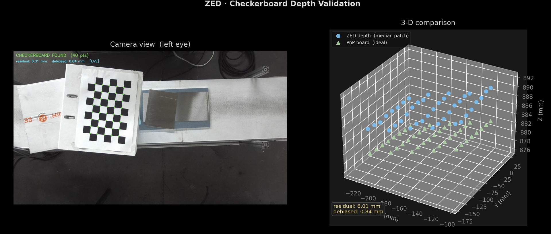
The dataflow here is:
Checkerboard image → solvePnP → ideal 3D points
Checkerboard image + ZED PCD→ sample Points @ HW idxs → measured 3D points
PNP 3D vs. measured 3D → residual metrics
Visualize (Live or on Trigger)
Here is the Code:
"""
ZED Checkerboard Depth Validation
==================================
Compares the "ideal" board pose (from solvePnP) with the raw depth point cloud
from the ZED camera. Two quality metrics are displayed:

  mean_residual         — mean 3-D distance between PnP corners and ZED cloud (mm)
  mean_residual_debiased — same, after removing the mean systematic offset (mm)

LIVE_MODE = True   → runs continuously, ~2 fps, useful for real-time monitoring
LIVE_MODE = False  → "trigger" mode: grab one frame, show it, wait for the
                     user to close the window, then capture the next frame
"""

import pyzed.sl as sl
import cv2
import numpy as np
import matplotlib.pyplot as plt
import time

# ─────────────────────────────────────────────
# Configuration
# ─────────────────────────────────────────────

LIVE_MODE = True          # True = continuous loop | False = close-window trigger

CHECKERBOARD  = (8, 5)    # inner corner count (cols, rows)
SQUARE_SIZE   = 236.0 / 9.0  # physical square size in mm

# Median-window half-size: samples a (2W+1)² patch around each corner
DEPTH_PATCH_HALF_SIZE = 1         # → 3×3 patch

# Only used in LIVE_MODE to cap CPU usage (~2 fps)
LIVE_SLEEP = 0.08      # seconds between frames


# ─────────────────────────────────────────────
# ZED camera initialisation
# ─────────────────────────────────────────────

zed = sl.Camera()

init_params                     = sl.InitParameters()
init_params.camera_resolution   = sl.RESOLUTION.HD2K
init_params.depth_mode          = sl.DEPTH_MODE.NEURAL
init_params.coordinate_units    = sl.UNIT.MILLIMETER
init_params.depth_stabilization = 0

if zed.open(init_params) != sl.ERROR_CODE.SUCCESS:
    raise RuntimeError("Failed to open ZED camera")

runtime = sl.RuntimeParameters()
if hasattr(sl, "SENSING_MODE"):
    runtime.sensing_mode = sl.SENSING_MODE.STANDARD


# ─────────────────────────────────────────────
# Camera intrinsics (left eye)
# ─────────────────────────────────────────────

calib  = zed.get_camera_information().camera_configuration.calibration_parameters
fx, fy = calib.left_cam.fx, calib.left_cam.fy
cx, cy = calib.left_cam.cx, calib.left_cam.cy

print(f"ZED intrinsics  fx={fx:.2f}  fy={fy:.2f}  cx={cx:.2f}  cy={cy:.2f}")

camera_matrix = np.array([[fx, 0, cx],
                           [0, fy, cy],
                           [0,  0,  1]], dtype=np.float64)

distortion_coeffs = np.array(calib.left_cam.disto) if hasattr(calib.left_cam, "disto") else None


# ─────────────────────────────────────────────
# ZED data containers
# ─────────────────────────────────────────────

zed_image       = sl.Mat()
zed_point_cloud = sl.Mat()


# ─────────────────────────────────────────────
# 3-D object points for the checkerboard model (mm)
# Layout: row-major grid, Z=0 (flat board assumption)
# ─────────────────────────────────────────────

board_model_pts = np.zeros((CHECKERBOARD[0] * CHECKERBOARD[1], 3), np.float32)
board_model_pts[:, :2] = np.mgrid[0:CHECKERBOARD[0],
                                   0:CHECKERBOARD[1]].T.reshape(-1, 2)
board_model_pts *= SQUARE_SIZE


# ─────────────────────────────────────────────
# Matplotlib figure setup
# ─────────────────────────────────────────────

# Dark background gives better contrast for the coloured scatter points
plt.style.use("dark_background")

plt.ion()
fig = plt.figure(figsize=(14, 6))
fig.suptitle("ZED · Checkerboard Depth Validation", fontsize=13,
             color="#e0e0e0", fontweight="bold")

ax_image  = fig.add_subplot(1, 2, 1)
ax_scatter3d = fig.add_subplot(1, 2, 2, projection="3d")

fig.tight_layout(rect=[0, 0, 1, 0.95])


# ─────────────────────────────────────────────
# Helper: robust depth sampling
# ─────────────────────────────────────────────

def sample_depth_patch(point_cloud_data, pixel_x, pixel_y, half_window):
    """
    Return the median (X, Y, Z) in a (2·half_window+1)² patch around pixel (pixel_x, pixel_y).
    Ignores pixels with non-finite or non-positive depth.
    Returns None when no valid sample is found in the patch.
    """
    img_h, img_w = point_cloud_data.shape[:2]
    patch_x_vals, patch_y_vals, patch_z_vals = [], [], []

    for row_offset in range(-half_window, half_window + 1):
        for col_offset in range(-half_window, half_window + 1):
            sample_x = pixel_x + col_offset
            sample_y = pixel_y + row_offset
            if 0 <= sample_x < img_w and 0 <= sample_y < img_h:
                point = point_cloud_data[sample_y, sample_x]
                if np.isfinite(point[2]) and point[2] > 0:
                    patch_x_vals.append(point[0])
                    patch_y_vals.append(point[1])
                    patch_z_vals.append(point[2])

    if not patch_z_vals:
        return None
    return [np.median(patch_x_vals), np.median(patch_y_vals), np.median(patch_z_vals)]


# ─────────────────────────────────────────────
# Main loop
# ─────────────────────────────────────────────

while True:

    # ── Grab frame ──────────────────────────────
    if zed.grab(runtime) != sl.ERROR_CODE.SUCCESS:
        continue

    zed.retrieve_image(zed_image, sl.VIEW.LEFT)
    zed.retrieve_measure(zed_point_cloud, sl.MEASURE.XYZ)

    raw_frame        = zed_image.get_data().copy()
    point_cloud_data = zed_point_cloud.get_data().copy()

    frame_bgr  = cv2.cvtColor(raw_frame, cv2.COLOR_BGRA2BGR)
    frame_gray = cv2.cvtColor(frame_bgr, cv2.COLOR_BGR2GRAY)


    # ── Checkerboard detection ───────────────────
    board_found, detected_corners = cv2.findChessboardCorners(
        frame_gray,
        CHECKERBOARD,
        flags=cv2.CALIB_CB_ADAPTIVE_THRESH | cv2.CALIB_CB_NORMALIZE_IMAGE,
    )

    zed_corner_pts   = []
    pnp_corner_pts   = None
    mean_residual         = None
    mean_residual_debiased = None

    if board_found:
        # Sub-pixel refinement for corner accuracy
        detected_corners = cv2.cornerSubPix(
            frame_gray, detected_corners, (11, 11), (-1, -1),
            (cv2.TERM_CRITERIA_EPS + cv2.TERM_CRITERIA_MAX_ITER, 30, 0.001),
        )

        # ── solvePnP → ideal board pose ─────────────
        _, rotation_vec, translation_vec = cv2.solvePnP(
            board_model_pts, detected_corners, camera_matrix, distortion_coeffs
        )
        rotation_mat, _ = cv2.Rodrigues(rotation_vec)

        # Transform flat board model corners into camera space
        pnp_corner_pts = (rotation_mat @ board_model_pts.T).T + translation_vec.reshape(1, 3)

        # ── ZED point cloud sampling ─────────────────
        # For every detected corner: take the median of a small patch to
        # suppress depth noise and stereo matching artefacts
        for (corner_x, corner_y) in detected_corners.reshape(-1, 2):
            sampled_pt = sample_depth_patch(
                point_cloud_data, int(corner_x), int(corner_y), DEPTH_PATCH_HALF_SIZE
            )
            if sampled_pt is not None:
                zed_corner_pts.append(sampled_pt)

        zed_corner_pts = np.array(zed_corner_pts)

        # ── Quality metrics ──────────────────────────
        if len(zed_corner_pts) == len(pnp_corner_pts):
            per_corner_residuals = zed_corner_pts - pnp_corner_pts
            per_corner_distances = np.linalg.norm(per_corner_residuals, axis=1)

            # mean_residual — raw mean 3-D distance; captures offset + shape error
            mean_residual = np.mean(per_corner_distances)

            # mean_residual_debiased — removes the mean systematic offset first,
            # so only shape/warp error remains (ignores a global depth shift)
            systematic_offset = np.mean(per_corner_residuals, axis=0)
            debiased_residuals = per_corner_residuals - systematic_offset
            mean_residual_debiased = np.mean(np.linalg.norm(debiased_residuals, axis=1))


    # ── 2-D overlay ─────────────────────────────
    display_frame = frame_bgr.copy()

    if board_found:
        status_text  = f"CHECKERBOARD FOUND  ({len(detected_corners)} pts)"
        status_color = (80, 220, 80)
        for (corner_x, corner_y) in detected_corners.reshape(-1, 2):
            cv2.circle(display_frame, (int(corner_x), int(corner_y)), 6, (80, 220, 80), -1)
    else:
        status_text  = "CHECKERBOARD NOT FOUND"
        status_color = (60, 60, 220)

    cv2.putText(display_frame, status_text, (20, 45),
                cv2.FONT_HERSHEY_SIMPLEX, 1.1, status_color, 2, cv2.LINE_AA)

    if mean_residual is not None:
        mode_tag = "LIVE" if LIVE_MODE else "TRIGGER"
        cv2.putText(
            display_frame,
            f"residual: {mean_residual:.2f} mm   debiased: {mean_residual_debiased:.2f} mm   [{mode_tag}]",
            (20, 90),
            cv2.FONT_HERSHEY_SIMPLEX, 0.85, (240, 220, 50), 2, cv2.LINE_AA,
        )


    # ── Matplotlib update ────────────────────────

    # Left panel — annotated camera image
    ax_image.clear()
    ax_image.imshow(cv2.cvtColor(display_frame, cv2.COLOR_BGR2RGB))
    ax_image.set_title("Camera view  (left eye)", color="#c8c8c8", pad=8)
    ax_image.axis("off")

    # Right panel — 3-D scatter comparison
    ax_scatter3d.clear()
    ax_scatter3d.set_facecolor("#111111")

    if len(zed_corner_pts) > 0:
        ax_scatter3d.scatter(
            zed_corner_pts[:, 0], zed_corner_pts[:, 1], zed_corner_pts[:, 2],
            c="#4fc3f7", s=40, label="ZED depth  (median patch)",
            depthshade=True, alpha=0.9,
        )

    if pnp_corner_pts is not None:
        ax_scatter3d.scatter(
            pnp_corner_pts[:, 0], pnp_corner_pts[:, 1], pnp_corner_pts[:, 2],
            c="#a5d6a7", s=40, marker="^", label="PnP board  (ideal)",
            depthshade=True, alpha=0.9,
        )

    ax_scatter3d.set_xlabel("X (mm)", labelpad=6, color="#aaaaaa")
    ax_scatter3d.set_ylabel("Y (mm)", labelpad=6, color="#aaaaaa")
    ax_scatter3d.set_zlabel("Z (mm)", labelpad=6, color="#aaaaaa")
    ax_scatter3d.tick_params(colors="#888888")
    ax_scatter3d.set_title("3-D comparison", color="#c8c8c8", pad=8)

    legend = ax_scatter3d.legend(loc="upper left", fontsize=8,
                                 framealpha=0.3, edgecolor="#555555")
    for legend_label in legend.get_texts():
        legend_label.set_color("#dddddd")

    # Metric annotation inside the 3-D panel
    if mean_residual is not None:
        ax_scatter3d.text2D(
            0.02, 0.06,
            f"residual: {mean_residual:.2f} mm\ndebiased: {mean_residual_debiased:.2f} mm",
            transform=ax_scatter3d.transAxes,
            color="#ffe082", fontsize=9, va="bottom",
            bbox=dict(boxstyle="round,pad=0.3", fc="#1a1a1a", ec="#555555", alpha=0.8),
        )

    plt.pause(0.001)


    # ── Frame-rate / trigger control ─────────────
    if LIVE_MODE:
        # Continuous mode: just throttle to ~2 fps
        time.sleep(LIVE_SLEEP)
    else:
        # Trigger mode: block until the user closes the figure window,
        # then immediately re-open it for the next capture.
        plt.ioff()
        plt.show(block=True)   # blocks here; user closes window to advance
        plt.ion()
        # Recreate the figure so the next frame has a fresh window
        fig = plt.figure(figsize=(14, 6))
        fig.suptitle("ZED · Checkerboard Depth Validation", fontsize=13,
                     color="#e0e0e0", fontweight="bold")
        ax_image     = fig.add_subplot(1, 2, 1)
        ax_scatter3d = fig.add_subplot(1, 2, 2, projection="3d")
        fig.tight_layout(rect=[0, 0, 1, 0.95])


# ─────────────────────────────────────────────
# Cleanup
# ─────────────────────────────────────────────
zed.close()